Circuit Diagram Of Galvanometer. The galvanometer is the device used for detecting the presence of small current and voltage or for measuring their magnitude. Apparatus and material required a moving coil galvanometer.
What is Galvanometer? Definition, Construction & Working Principle from circuitglobe.com
Web circuit diagram for determination of galvanometer resistance g the circuit is connected as shown in fig. It can be converted into an ammeter to measure the currents in. Web the torsion springs are also made of a conducting material.
Circuit Diagram Of Shunt And.
As the current flows from + through the coil (the orange part) to − , a magnetic field is generated in the coil. When the galvanometers in each arrangement do not show any deflection, obtain the ratio r 1 /r 2. Web figure shows two circuits each having a galvanometer and a battery of 3v.
The Loop Of Wire Is Also.
Web figure shows two circuits each having a galvanometer and a battery of 3 v.when the galvanometers in each arrangement do not show any deflection,obtain the ratio r 2. Web the circuit diagram for a galvanometer converted into a voltmeter is as follows: Web galvanometer, instrument for measuring a small electrical current or a function of the current by deflection of a moving coil.
Here Rg R G Is The Resistance Of The Galvanometer And Rs R S Is The Shunt Resistance.
Theory let the current flowing through the. It can be converted into an ammeter to measure the currents in. The galvanometer can be converted into a voltmeter by connecting a high resistance in series with it.
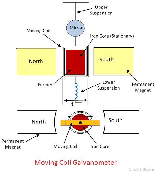
Apparatus And Material Required A Moving Coil Galvanometer.
Web circuit diagram for determination of galvanometer resistance g the circuit is connected as shown in fig. Web in this topic, you study the construction, diagram, derivation & working of galvanometer. Web the circuit diagram represents a galvanometer combined with a shunt resistor.
In The Above Circuit Diagram, The Galvanometer G Is Connected In The Circuit.
Web diagram of d'arsonval/weston type galvanometer. Web which of the following circuit diagrams most correctly represents a galvanometer combined with a multiplier resistor being used as a voltmeter to measure the voltage of a. The galvanometer is the device used for detecting the presence of small current and voltage or for measuring their magnitude.